Femto Bolt Documentation
产品详情描述
Overview
产品下分类文档描述
About Femto Bolt
About Femto Bolt Contents Orbbec SDK and Orbbec SDK K4A Wrapper Human Skeleton Tracking SDK Femto Bolt Hardware Requirements Next Steps
Femto Bolt is an advanced iToF 3D camera jointly developed by Orbbec and Microsoft. The depth camera uses Microsoft’s latest advanced ToF sensing technology and has a working mode and performance that is completely consistent with the Microsoft AKDK depth camera.
The Femto Bolt 3D camera integrates multiple sensing methods including multi-mode depth camera, color video camera and inertial sensor, and can simultaneously realize data transmission and power supply to the camera through a single USB Type-C connection. At the same time, Microsoft recommends using Femto Bolt as an alternative to Azure Kinect DK. For details, please refer to:
https://techcommunity.microsoft.com/t5/mixed-reality-blog/microsoft-s-azure-kinect-developer-kit-technology-transfers-to/ba-p/3899122 Femto Bolt can be purchased at Femto Bolt Purchase Link.
The Femto Bolt development environment consists of several SDKs:
Orbbec SDK K4A Wrapper or Orbbec SDK for accessing the device. Human Skeleton Tracking SDK for tracking 3D human bodies. In addition, Cognitive Vision services can be used with the device RGB camera. The system architecture diagram using Orbbec SDK K4a Wrapper is as follows:
The system architecture diagram using Orbbec SDK directly is as follows:
Note: Using only Orbbec SDK without Orbbec SDK K4a Wrapper cannot use AKDK’s skeleton tracking algorithm.
Orbbec SDK and Orbbec SDK K4A Wrapper Orbbec Femto Bolt is a reliable alternative product to Microsoft Azure Kinect DK. We provide two SDKs for this product: Orbbec SDK and Orbbec SDK K4A Wrapper.Since Orbbec cannot provide upgrades and maintenance of the original AKDK development tools, from a long-term perspective, we recommend that you try and use Orbbec SDK that Orbbec has been maintaining and updating as soon as possible. Using Orbbec SDK with Femto Bolt will give you richer and more powerful features.To help users who have developed applications using K4A get started with Orbbec Femto Bolt more quickly, and achieve seamless replacement of Microsoft AKDK. On top of Orbbec SDK, we encapsulated Orbbec SDK K4A Wrapper that is maximally compatible with K4A API. Using this Wrapper, users basically don’t need to modify their application code.Orbbec SDK and Orbbec SDK K4A Wrapper provide access to complete Femto Bolt hardware sensor and device configuration.For more information on Orbbec SDK and Orbbec SDK K4A Wrapper, please refer to 《Using Orbbec SDK K4A Wrapper》 Orbbec SDK Features Orbbec SDK is the native SDK for Orbbec Femto Bolt and can use all the features of Femto Bolt:
Depth camera access, resolution and frame rate control (including passive IR mode) RGB camera access, resolution, frame rate and image effect control (e.g. exposure, white balance, mirroring) IMU (gyroscope and accelerometer) access, sampling rate and range control Hardware synchronization of depth and color cameras and software synchronization (match by frame timestamp to achieve software synchronization) on the SDK side, configurable inter-camera delay External device synchronization control, configurable inter-device delay offset Free Run mode enables different frame rate configurations for depth and color cameras Access camera frame metadata for handling image resolution, timestamps, etc. Access to device calibration data Utility filters such as color image format conversion, point cloud data generation Depth data stream output aligned to color (i.e. D2C, output depth coordinate system and image resolution consistent with RGB) Complete setting information acquisition (device name, firmware version, SN, device temperature, etc.) Data recording function supports data compression Native C/C++ API and Python, ROS1, ROS2, Android wrappers In addition, Orbbec SDK also supports almost all Orbbec’s mainstream cameras.
Orbbec SDK K4A Wrapper Features Orbbec SDK and Orbbec SDK K4A Wrapper provide the following features that can run on Femto Bolt once installed:
Depth camera access and mode control (passive IR mode, wide field-of-view and narrow field-of-view depth modes) RGB camera access and control (e.g. exposure and white balance) Motion sensor (gyroscope and accelerometer) access Synchronized depth and RGB camera streams with configurable inter-camera delay External device synchronization control with configurable inter-device delay offset Access camera frame metadata for handling image resolution, timestamps, etc. Access device calibration data Femto Bolt SDK Tools Orbbec SDK K4A Wrapper provides the following tools:
Viewer tool that can be used to monitor device data streams and configure different modes Sensor recording tool and playback reader API using Matroska container format
Human Skeleton Tracking SDK The human skeleton tracking algorithm SDK uses Microsoft’s human skeleton tracking algorithm, namely: Azure Kinect Body Tracking SDK.To use the human skeleton tracking algorithm on Femto Bolt hardware, please refer to:Azure Kinect Body Tracking Features Access AKDK Applications with Femto Bolt Femto Bolt supports accessing Azure Kinect Body Tracking SDK to obtain human body tracking features and effects completely consistent with using AKDK:
Provides human image segmentation Skeletons of partial or full bodies within the FOV range Provides unique identification for each human body Can track human bodies in real time Azure Kinect Body Tracking Tools After accessing Azure Kinect Body Tracking SDK with Femto Bolt, the following functions can be supported using the viewer tool in this SDK:
The body tracker provides a viewer tool to see how it tracks 3D human bodies.
Femto Bolt Hardware Requirements Femto Bolt is a high performance iToF 3D camera jointly developed by Orbbec and Microsoft. The camera uses the same depth module as Azure Kinect DK, continuing the same depth modes and performance. For details, please refer to Hardware Specifications.
Next Steps Now that you have a preliminary understanding of Femto Bolt, please go in depth into its various functions and make corresponding settings! Quick Start: 《Hardware Specifications》,《Set up Femto Bolt》
Femto Bolt Comparison with Azure Kinect DK
Femto Bolt Comparison with Azure Kinect DK Microsoft announced the end of sale and transfer of the Azure Kinect DK to a partner system in Aug 2023. Orbbec’s Femto Bolt is the commercial alternate to Microsoft’s Azure Kinect DK that uses Microsoft’s industry-proven iToF technology and has identical depth camera operating modes and performance. It is a compact, high-performance device with multi-mode Depth and RGB cameras, internal IMU and USB-C connection for power and data.
This document provides valuable information for developers transitioning to ORBBEC® Femto Bolt from the Microsoft Azure Kinect DK.
Comparison of Product Features with Azure Kinect DK Key Features Femto Bolt Azure Kinect DK Depth identical operating modes and performance
Depth image to Color accuracy Optimized to max<4 pixel; mean<2 pixel max<15.05 pixel; mean<7.8 pixel RGB FOV Slightly reduced to H80° V51° H90° V59° RGB HDR support Supported Not supported Device size More compact, only 64.9mm deep Depth dimension: 125.4mm Multi-camera sync 8-pins for extended functions 2 pin audio cable Power consumption 7.5W max (4.0W avg.) 5.9W max Data interface Dual screw locking USB-C USB-C SDK Orbbec SDK with Orbbec SDK K4A Wrapper
Azure Kinect Sensor SDK For details on Femto Bolt hardware specifications, please refer to Hardware Specifications.
Detailed Comparison with the Azure Kinect DK ● Depth Cameras Femto Bolt integrates Microsoft’s 1 megapixel Time-of-Flight (ToF) depth camera that is used in the Azure Kinect DK, and provides identical operating modes and performance as described below:
Mode Resolution FoV FPS Operating Range* Exposure Time NFOV unbinned 640×576 75°x65° 5, 15, 25, 30 0.5 – 3.86 m 12.8 ms NFOV 2×2 binned (SW) 320×288 75°x65° 5, 15, 25, 30 0.5 – 5.46 m 12.8 ms WFOV 2×2 binned 512×512 120°x120° 5, 15, 25, 30 0.25 – 2.88 m 12.8 ms WFOV unbinned 1024×1024 120°x120° 5, 15 0.25 – 2.21 m 20.3 ms Passive IR 1024×1024 N/A 5, 15, 25, 30 N/A 1.6 ms *850nm at 15% to 95% reflectivity, 2.2 μW/cm2/nm, standard deviation of random error ≤ 17 mm, typical system error < 11 mm + 0.1% of distance (no multi-path interference).
Depth may be provided beyond the indicated operating range depending on object reflectivity.
● SDK Compatibility The Femto Bolt uses Orbbec SDK for setup and control. In addition, Orbbec has developed the Orbbec SDK K4A Wrapper to make it easier for applications developed based on Azure Kinect DK to be switched to the Femto Bolt. For detailed instructions, please refer to Orbbec SDK K4A Wrapper on GitHub.
● RGB Camera The Femto Bolt RGB camera provides the same resolution as the Azure Kinect DK (3840 x 2160@30fps), but with a slightly smaller FOV. However, the Femto Bolt RGB camera supports HDR, has a high dynamic range and can provide higher quality RGB images and videos.
Femto Bolt Azure Kinect DK RGB FOV H80° V51° H90° V59° RGB HDR Supported Not supported RGB dynamic range Improved to 81.1DB 45.6DB Comparison of color images:
The table below shows a comparison of the camera field of view (what the sensor “sees”) for depth and RGB cameras at a distance of 2m.
Comparison of color performance:
The detailed specification comparison of the color cameras is shown in the table below:
Color Camera Characteristics Femto Bolt Azure Kinect DK Pixel pitch 1.45 um 1.25 um Sensor Size 5.568×3.840mm 5.120×3.132 mm F number 2.7 2.2 Aspect Ratio 16:9 4:3 RGB camera resolution (HxV) and Aspect ratio Frame rate (FPS) Format options FOV (HxV) Frame rate (FPS) Format options FOV (HxV) 3840×2160 16:9 0, 5, 15, 25, 30 MJPEG
80°x51° 0, 5, 15, 30 MJPEG
90°x59° 2560×1440 16:9 0, 5, 15, 25, 30 MJPEG
80°x51° 0, 5, 15, 30 MJPEG
90°x59° 1920×1080 16:9 0, 5, 15, 25, 30 MJPEG
80°x51° 0, 5, 15, 30 MJPEG
90°x59° 1280×720 16:9 0, 5, 15, 25, 30 MJPEG/YUY2/NV12
80°x51° 0, 5, 15, 30 MJPEG/YUY2/NV12
90°x59° 4096×3072 4:3 N/A 0, 5, 15 MJPEG
90°x74.3° 2048×1536 4:3 N/A 0, 5, 15, 30 MJPEG
90°x74.3° 1280×960 4:3 0, 5, 15, 25, 30 MJPEG
65°x51° N/A ● D2C Optimization Improvements of D2C accuracy of the Femto Bolt are shown below.
Comparison of foreground and background boundary alignment:
● SDK Difference Orbbec SDK K4A Wrapper Interface Differences
No. Function Point Orbbec SDK K4A Wrapper Azure Kinect Sensor SDK Impact on Application 1 Recording c++ typedef struct _k4a_record_configuration_t { /** * The timestamp offset of the start of the recording. All recorded timestamps are offset by this value such that * the recording starts at timestamp 0. This value can be used to synchronize timestamps between 2 recording files. / uint64_t start_timestamp_offset_usec; } k4a_record_configuration_t; c++ typedef struct _k4a_record_configuration_t { /* * The timestamp offset of the start of the recording. All recorded timestamps are offset by this value such that * the recording starts at timestamp 0. This value can be used to synchronize timestamps between 2 recording files. */ uint32_t start_timestamp_offset_usec; } k4a_record_configuration_t; Need to replace and recompile the header file with Orbbec SDK K4a Wrapper Orbbec SDK K4A Wrapper Unimplemented Interfaces (Return Empty Value or Exception State)
No. Azure Kinect Sensor SDK Interface Meaning 1 c++ k4a_result_t k4a_set_allocator(k4a_memory_allocate_cb_t allocate, k4a_memory_destroy_cb_t free) Pass in external user-defined memory manager for SDK internal memory application
2 c++ void k4a_capture_set_temperature_c(k4a_capture_t capture_handle, float temperature_c) Set temperature information for capture
3 c++ float k4a_capture_get_temperature_c(k4a_capture_t capture_handle) Get temperature information for capture
4 c++ void k4a_image_set_exposure_usec(k4a_image_t image_handle, uint64_t exposure_usec) Set exposure value for image
5 c++ void k4a_image_set_white_balance(k4a_image_t image_handle, uint32_t white_balance) Set white balance value for image
6 c++ void k4a_image_set_iso_speed(k4a_image_t image_handle, uint32_t iso_speed) Set ISO speed for image
7 c++ uint64_t k4a_image_get_exposure_usec(k4a_image_t image_handle) Get exposure value for image
8 c++ uint32_t k4a_image_get_white_balance(k4a_image_t image_handle) Get white balance value for image
9 c++ uint32_t k4a_image_get_iso_speed(k4a_image_t image_handle) Read ISO speed for image
10 c++ k4a_result_t k4a_device_get_sync_jack(k4a_device_t device_handle, bool *sync_in_jack_connected, bool *sync_out_jack_connected) Get sync cable connection status for device
● Mechanical Femto Bolt is much more compact with about half the depth of the Azure Kinect DK. The spacing between the M2.5 x 4mm mounting screws on the sides had to be reduced.
The USB-C connector can be locked using two screws to enhance mechanical stability and data transmission.
● Multi-Camera Synchronization Function Femto Bolt uses a 8-pin interface with extended and precise synchronization capability compared to the 2 pin audio cable used by Azure Kinect DK.
Electrical integration Femto Bolt Azure Kinect DK Multi-camera synchronization interface 8-pin interface Sync-out, Sync-in Orbbec’s 8-pin design combines the sync in and sync out port with advanced trigger control through the SDK. And the trigger voltage is switchable (1.8V, 3.3V, 5V). The number of secondary devices can be extended using multiple hubs.
Orbbec’s Sync Hubs are available in two versions, the Sync Hub Dev and Sync Hub Pro, and are designed to reduce the complexity and cost of a multi-camera network of compatible Orbbec cameras and external sensors.
The Developer edition is effective for rapid prototyping during early-stage development. The Professional edition, designed for commercial use, employs a reliable RJ45 interface for a more stable and longer-range signal connection using standard CAT5 or better cables.
When using Orbbec SDK K4A Wrapper, the Femto Bolt multi-camera synchronization function and operation flow are basically consistent with Azure Kinect DK, but:
Femto Bolt does not support sync cable status detection. The Femto Bolt multi-camera synchronization scheme is asynchronous time assignment, while Azure Kinect DK is synchronous reset to zero, which may cause the timestamps to fail to synchronize when multiple Femto Bolts are currently connected to different hosts and used through Orbbec SDK K4A Wrapper. SDK and application layer differences are described in detail:
Module Function Femto Bolt + Orbbec SDK K4A Wrapper Femto Bolt + Orbbec SDK Azure Kinect DK Multi machine timestamp synchronization
Timestamp synchronization clearing N/A Freely configurable and triggered via the interface Zeroing of the first frame after opening the stream in primary and secondary modes Asynchronous timing (PC timing to each device) Timing is turned on by default when the device is turned on Timing can be performed freely through the interface N/A Synchronization cable Connection Status Detection N/A N/A Sync in jack and sync out jack connection detection
Simultaneous Image Acquisition
Synchronization mode within the camera In standalone mode, depth and RGB are synchronized. In standalone mode, depth and RGB are synchronized. In Free Run mode, depth and RGB are individually configurable (No synchronization, different frame rates configurable)
Standalone mode, depth and RGB synchronization Multi-computer synchronization mode Primary + Secondary Primary + Secondary Primary + Secondary Primary-Secondary Delay Configuration Support for configuring the delay of the secondary device relative to the primary device (via depthDelay) Supports depthDelay, colorDelay, triggerOutDelay Supports configuration of secondary relative to primary delay Depth and RGB Delay Configuration Support for configuring depth or RGB delays (via depthDelay and ColorDelay) Support depthDelay, colorDelay Supports configuration of depth or RGB delay Primary-Secondary opening sequence Recommend turning on the secondary first Recommend turning on the secondary first Required to turn on the secondary first. For related instructions, please refer to: Synchronize Multiple Devices
● Other Electrical Differences Electrical Integration Femto Bolt Azure Kinect DK DC DC 12V/2A DC plug dimensions:
Inner diameter = 2.1mm; Outer diameter = 5.5mm; Pin diameter = 0.6mm
DC 5.2V/2.5A DC plug dimensions:
Inner diameter = 3.0mm; Outer diameter = 4.5mm; Pin diameter = 0.6mm
Multi-camera sync interface 8-pin interface Sync-out, Sync-in Average power consumption 4.35W 3.9W Max power consumption Max power consumption < 8.8W Max power consumption < 5.9W ● IMU IMU Femto Bolt Azure Kinect DK IMU sampling frequency Default 500Hz, supports 50Hz, 100Hz, 200Hz, 500Hz, 1KHz, 2KHz 1.6 kHz
Quickstarts
产品下分类文档描述
Set up Femto Bolt
Set up Femto Bolt
This quickstart provides guidance on how to set up your Femto Bolt, including how to test 3D camera stream visualization and use associated capabilities.
System Requirements Review the Hardware Specificationsto verify your host computer configuration meets all minimum requirements for Femto Bolt.
Set up Hardware Note: Make sure to remove the protective film from the camera prior to use.
Insert the power connector into the power jack on the back of the device. Connect the USB power adapter to the other end of the cable, then plug the adapter into a power outlet. Connect one end of the USB data cable to the device and the other end to a USB 3.0 port on your PC. Note: For best results, connect cables directly to the device and computer. Avoid extenders or additional adapters in connections.
Verify the power indicator LED (next to the USB cable) is solid white. It takes a few seconds for the device to power on. The device is ready for use when the streaming LED indicator on the front goes out.
For details on the power indicator LED, see Hardware Specifications.
Download the SDK Go to the Orbbec SDK and K4A Wrapperdownload link. Install the SDK on your PC.
Update Firmware The latest firmware version is required for the SDK to function properly. To check and update the firmware version, follow the steps in Update Femto Bolt Firmware.
Verify Device Streams Data Launch the K4A Viewer Tool, either from the command line or by double clicking. In the Femto Bolt Viewer, select “Open Device” > “Start”. Verify the tool visualizes each sensor stream: Depth camera Color camera Infrared camera IMU
Femto Bolt setup is now complete. You can now start developing applications.
If you encounter any issues, check out Femto Bolt Troubleshooting.
Next Steps With your Femto Bolt up and running, you can also learn how to:Record data to file
Record data to file
Quickstart: Femto Bolt Data Recording
This quickstart provides information on how to use the K4A recorder tool to record the data streams emitted from the Sensor SDK to a file.
Prerequisites Femto Bolt is connected to the host computer and powered on properly. You have completed Set up Femto Bolt.
Create Recording Open a command prompt, providing the path to k4arecorder.exe, located in the k4arecorder tool install location. For example: F:\OrbbecSDK_K4A_Wrapper_v1.8.1_20231011_win_x64_release\bin\k4arecorder.exe
Record for 5 seconds: k4arecorder.exe -l 5 output.mkv
By default, the recorder captures content with NFOV unbinned depth mode, 1080p RGB @ 30 fps (including IMU data). See K4A Recorder for Femto Bolt , a full overview and tips on recording options.
Play Recording You can play back the recording using the K4A Viewer tool.
Launch k4aviewer.exe Expand the “Open Recording” tab and open your recording.
Next Steps You now know how to record sensor streams to file, next you can generate your first application.
Let me know if you need any clarification or have feedback on the translation!
Concepts
产品下分类描述
Depth Camera
Depth Camera
This page describes how to use the depth camera in Femto Bolt. The depth camera is the second of two cameras. As described in earlier sections, the other camera is the RGB camera.
Working Principle
The Femto Bolt depth camera uses amplitude modulated continuous wave (AMCW) time-of-flight (ToF) principles. The camera projects modulated light in the near infrared (NIR) spectrum into the scene. It then records an indirect measurement of the time it takes for the light to travel from the camera to the scene and back.Processing these measurements can produce a depth frame. A depth frame consists of Z-coordinates in millimeters corresponding to each pixel in the image.
Along with the depth frame, we also get what are known as Active IR readings. The pixel values in the Active IR correspond to the amount of light returned from the scene. This image looks similar to a conventional IR image. The image below shows a sample depth frame (left) and its corresponding Active IR image (right).
Key Capabilities
Key capabilities of the depth camera include:
1 megapixel ToF imaging chip with advanced pixel techniques for higher modulation frequency and depth accuracy.
Two NIR laser diodes for near and wide field-of-view (FoV) depth modes.
World’s smallest 3.5μm x 3.5μm ToF pixels.
Auto pixel gain selection enables larger dynamic range, allowing sharp capture of both near and far objects.
Global shutter helps improve daylight capture performance.
Multi-phase depth computation method enables reliable accuracy even with chip, laser, and power variations.
Low system error and random error.
The depth camera streams the raw modulated IR images to the PC host. On the PC, GPU accelerated depth engine software converts the raw signal into depth frames. The depth camera supports several modes. The narrow field-of-view (FoV) mode works well for scenes with a small X,Y extent but a large Z extent. For scenes with a large X,Y extent but small Z extent, the wide FoV mode is more appropriate.
The depth camera supports a 2×2 binned mode which can extend the Z range compared to the unbinned modes. The tradeoff for binning is reduced image resolution. All modes can run at frame rates up to 30 frames/second (fps), except for the 1 megapixel (MP) mode which has a maximum frame rate of 15 fps. The depth camera also provides a Passive IR mode. In this mode, the illuminators on the camera are not activated and only ambient light can be observed.
Camera Performance
The performance of the camera is measured by the system error and random error.System Error
The system error is defined as the difference between the measured depth after denoising and the true (ground truth) depth. We calculate a temporal mean over many frames of a static scene to remove as much depth noise as possible. More specifically, the system error is defined as:
 Where d_t is the measured depth at time t, N is the number of frames used in the averaging process, and d_gt is the ground truth depth.
The system error specification for the depth camera does not include multi-path interference (MPI). MPI occurs when a sensor pixel integrates light reflected from multiple objects. Using a higher modulation frequency, as well as depth invalidations described shortly, can partially mitigate MPI in the depth camera.
Random Error
Suppose we capture 100 images of the same object without moving the camera. Across these 100 images, the object depth varies slightly in each image. This variation is caused by speckle noise. Speckle occurs because the number of photons striking the sensor fluctuates randomly for some reason. We define this random error in a static scene as the standard deviation of depth over time according to: [](https://gitbook.wiipoo.com/uploads/images/gallery/2025-02/image008-1.gif) Where N is the number of depth measurements, d_t is the depth measurement at time t, and d is the mean computed over all depth measurements d_t.Invalidations In some cases, the depth camera may be unable to provide correct values for some pixels. In these cases, the depth pixel is invalidated. Invalid pixels are indicated by a depth value of 0. Reasons the depth engine cannot produce a correct value include:
Outside active IR illumination mask
IR signal saturation
Low IR signal strength
Filtering anomalies
Multi-path interference
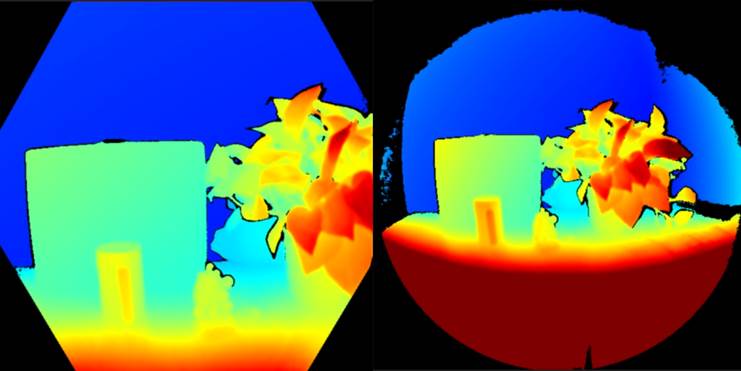
Illumination Mask
Pixels outside the active IR illumination mask will be invalidated. We do not recommend using the signal from such pixels to compute depth. The image below shows an example of pixel invalidations from being outside the illumination mask. Invalid pixels include the black pixels outside the circle in the wide FoV mode (left) and the hexagon in the narrow FoV mode (right).
Signal Strength
Pixels with a saturated IR signal will be invalidated. Phase information is lost when a pixel saturates. The image below shows an example of pixel invalidations from IR signal saturation. Notice the arrows pointing to example pixels in the depth image and IR image.
Pixels can also be invalidated if the IR signal strength is too low to produce valid depth. The image below shows an example of pixel invalidations from low IR signal strength. Again notice the arrows pointing to example pixels in the depth image and IR image.
Ambiguous Depth Pixels can also be invalidated if they receive signals from multiple objects in the scene. This commonly occurs around corners. Due to scene geometry, IR light emitted from the camera reflects off one wall onto another. This reflected light leads to ambiguous measured pixel depths. Filters in the depth algorithm detect these ambiguous signals and invalidate the pixels.
The image below shows an example of multi-path detection causing pixel invalidations. You can also observe how the same surface area invalidated in one camera view (top row) reappears in the other camera view (bottom row). This demonstrates surfaces invalidated in one perspective may be visible in another.
Multi-Path Mixing
Another common case of multi-path is when a pixel contains a mix of signals from foreground and background (e.g. around object edges). More invalidated pixels around edges may be noticeable in fast motion scenes. This is due to the exposure interval of the raw depth capture.
How-to guides
产品下分类描述
Tools
产品下分类描述
Resources
产品下分类描述