
Gemini 335Lg
Depth Camera
This page describes how to use the depth camera in Femto Bolt. The depth camera is the second of two cameras. As described in earlier sections, the other camera is the RGB camera.Overview:
Working AboutPrinciple
Processing these measurements can produce a depth frame. A depth frame consists of Z-coordinates in millimeters corresponding to each pixel in the image.
Quickstarts:Along —with Geminithe 330depth Seriesframe, Quickwe Startalso Guideget what are known as Active IR readings. The pixel values in the Active IR correspond to the amount of light returned from the scene. This image looks similar to a conventional IR image. The image below shows a sample depth frame (left) and its corresponding Active IR image (right).
Key Capabilities
Key capabilities of the depth camera include:
1 megapixel ToF imaging chip with advanced pixel techniques for higher modulation frequency and depth accuracy.
Two NIR laser diodes for near and wide field-of-view (FoV) depth modes.
World’s smallest 3.5μm x 3.5μm ToF pixels.
Auto pixel gain selection enables larger dynamic range, allowing sharp capture of both near and far objects.
Global shutter helps improve daylight capture performance.
Multi-phase depth computation method enables reliable accuracy even with chip, laser, and power variations.
Low system error and random error.
—The Exploredepth camera functionsstreams the raw modulated IR images to the PC host. On the PC, GPU accelerated depth engine software converts the raw signal into depth frames. The depth camera supports several modes. The narrow field-of-view (FoV) mode works well for scenes with a small X,Y extent but a large Z extent. For scenes with a large X,Y extent but small Z extent, the wide FoV mode is more appropriate.
The depth camera supports a 2×2 binned mode which can extend the Z range compared to the unbinned modes. The tradeoff for binning is reduced image resolution. All modes can run at frame rates up to 30 frames/second (fps), except for the 1 megapixel (MP) mode which has a maximum frame rate of 15 fps. The depth camera also provides a Passive IR mode. In this mode, the illuminators on the camera are not activated and only ambient light can be observed.
Camera Performance
The performance of the camera is measured by the system error and random error.System Error
The system error is defined as the difference between the measured depth after denoising and the true (ground truth) depth. We calculate a temporal mean over many frames of a static scene to remove as much depth noise as possible. More specifically, the system error is defined as:
 Where d_t is the measured depth at time t, N is the number of frames used in
 Orbbecthe Vieweraveraging process, and d_gt is the ground truth depth.
—The Geminisystem 335Lgerror Quickspecification Startfor the depth camera does not include multi-path interference (MPI). MPI occurs when a sensor pixel integrates light reflected from multiple objects. Using a higher modulation frequency, as well as depth invalidations described shortly, can partially mitigate MPI in the depth camera.
Random Error
Suppose we capture 100 images of the same object without moving the camera. Across these 100 images, the object depth varies slightly in each image. This variation is caused by speckle noise. Speckle occurs because the number of photons striking the sensor fluctuates randomly for some reason. We define this random error in a static scene as the standard deviation of depth over time according to: [](https://gitbook.wiipoo.com/uploads/images/gallery/2025-02/image008-1.gif) Where N is the number of depth measurements, d_t is the depth measurement at time t, and d is the mean computed over all depth measurements d_t.Invalidations In some cases, the depth camera may be unable to provide correct values for some pixels. In these cases, the depth pixel is invalidated. Invalid pixels are indicated by a depth value of 0. Reasons the depth engine cannot produce a correct value include:
Concepts:Outside —active IR illumination mask
IR signal saturation
Low IR signal strength
Filtering anomalies
Multi-path interference
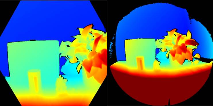
Illumination Mask
Pixels outside the active IR illumination mask will be invalidated. We do not recommend using the signal from such pixels to compute depth. The image below shows an example of pixel invalidations from being outside the illumination mask. Invalid pixels include the black pixels outside the circle in the wide FoV mode (left) and the hexagon in the narrow FoV mode (right).
Signal Strength
Pixels with a saturated IR signal will be invalidated. Phase information is lost when a pixel saturates. The image below shows an example of pixel invalidations from IR signal saturation. Notice the arrows pointing to example pixels in the depth image and IR image.
Pixels can also be invalidated if the IR signal strength is too low to produce valid depth. The image below shows an example of pixel invalidations from low IR signal strength. Again notice the arrows pointing to example pixels in the depth image and IR image.
Ambiguous Depth
qualityPixels metricscan also be invalidated if they receive signals from multiple objects in the scene. This commonly occurs around corners. Due to scene geometry, IR light emitted from the camera reflects off one wall onto another. This reflected light leads to ambiguous measured pixel depths. Filters in the depth algorithm detect these ambiguous signals and invalidate the pixels.
—The Metadataimage below shows an example of multi-path detection causing pixel invalidations. You can also observe how the same surface area invalidated in one camera view (top row) reappears in the other camera view (bottom row). This demonstrates surfaces invalidated in one perspective may be visible in another.
—Multi-Path OrbbecMixing
SDKAnother architecture
Datasheet:case —of Orbbecmulti-path Geminiis 330when seriesa datasheet
—contains Orbbeca Geminimix 335Lgof datasheet
How-from foreground and background (e.g. around object edges). More invalidated pixels around edges may be noticeable in fast motion scenes. This is due to guides:the —exposure Useinterval of the raw depth post-processingcapture.
blocks
— Use depth presets
Resources:
— Supported hosts & system requirements
— Orbbec SDK supported features
— Gemini 335Lg host platform adapted list
— Gemini 335Lg Recommended FAKRA Connector & Cable Specifications
— Regulatory compliance and certificates
Code samples & wrappers:
— C Sample Hello Orbbec
— C++ Sample Hello Orbbec
— ROS 1 Wrapper User Manual
— ROS 2 Wrapper User Manual